
For a Nixie clock I was designing, I needed a compact but functional and stable 170 V supply for upwards of 18 mA. The only available source on our board is 5 V, as we wanted this product to work on any USB supply that supported our current draw on 5 V to eliminate the need to buy a new power brick and reduce obsolescence (of older non-PD power bricks). This product should work on any USB supply.
Recently, I learned a lot about power supplies and gained a lot of practical knowledge about them. I want to improve this design so another post will follow up this one.
History
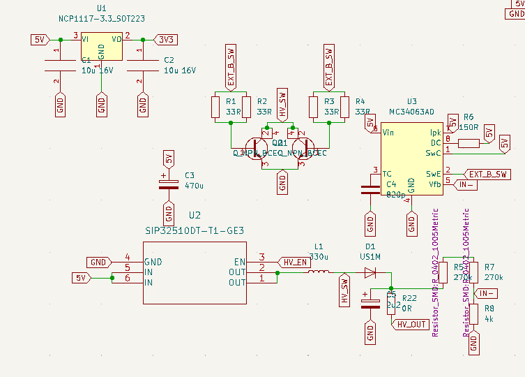
This proved to be a hard task, as the first variant, visible above, did not make it past the 40 V mark and worked better as a space heater than its own purpose. This circuit did not work due to the too-slow current switching in the MJD50G NPN Power transistors (Multiple were chosen to guarantee that the maximum current did not exceed their current ratings). Once I drove them with an IRFZ44N MOSFET, for which the MC34063 could deliver enough current, the voltage rose to 170V!
However, once even a small load was applied, the voltage once again dropped to 40 V, as the MC34063 switching converter could simply not keep up its duty cycle. Even with a ratio extender circuit found here (AN920D, ON Semiconductor), it did not suffice.
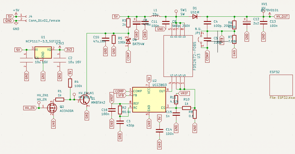
I completely abandoned this design and went with a DCM (Discontinuous Current Mode) design based on the UCC3803 IC and the FDS2672 N-channel MOSFET. For reference, I knew that this MOSFET and IC would work through this link, but I wanted to verify it and design it myself. I utilized this circuit and tweaked it a bit to my needs. At this point, I was not as familiar with power supply design as I am now. I have to add: I still have a lot to learn, one can never learn enough.
The design looked like this for revision 2:
Which after designing the PCB, looked like this:
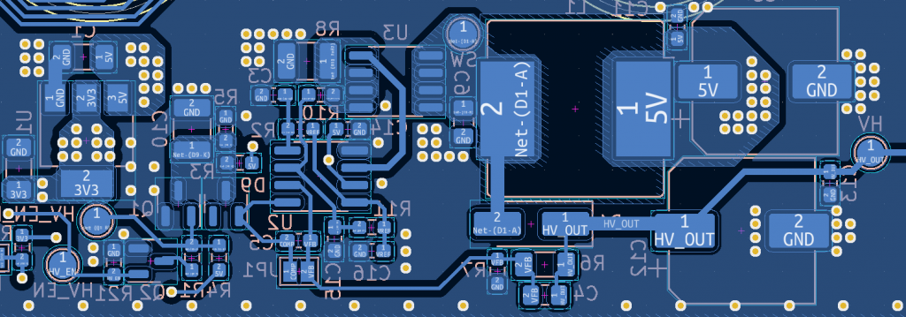
The large amount of vias is laid there to have a better current path. Along the edge they are there for EMC.
This time, the design functioned remarkably! However, the input voltage ripple was too high for my taste. Next to this, the location of the high-voltage diode is not ideal and has to be moved. This will be done in the next revision. A thing that is great about this design that it has an enable integrated by pulling the COMP pin to ground. I specifically needed an enable high for the entire circuit, as the 170 V should not be enabled before the HV IC is initialized to a known state, otherwise, the IC will be damaged.
Ripple analysis
To measure input ripple voltage for this step up converter, the channel is set to AC coupled, along with a bandwidth limit of 20 MHz, this is to remove really high frequency spikes, which are not taken into account when measuring ripple.
Under no load conditions, the input voltage ripple generated looks as follows

To make it more clear, the cursor was put there to show the actual ripple voltage ignoring the faint spikes visible in the picture. This gave a ripple voltage of 52 mV peak to peak, letting the input voltage fluctuate between 5.063 V and 5,011 V which is acceptable. However I want this number to be lower
The input voltage ripple under load looks like this, and it is more significant.

It has a 214 mV peak to peak ripple voltage making the input voltage fluctuate between 5.148 V and 4.934 V. This ripple voltage is too high for my liking at the input side under load. It should not pose an issue for the entire design, but it is best to improve it anyways.
Immediately obvious to me now is why the input voltage ripple is so high. I used an electrolytic capacitor for the input capacitor. These types of capacitors have a relatively large ESR compared to X5R and X7R dielectric MLCCs, which would also be suitable for input capacitors, as they can only handle low voltages. These will be used in the next revision to minimize the voltage ripple at the input. As a bonus, they are low profile.
The output voltage ripple is shown below under no load as

The minimum value visible here is -300 mV and the maximum voltage is 300 mV as well, bringing the output ripple to 600 mV total. This is very acceptable for these tubes and will pose no issue. To make this ripple smaller, I can choose to increase the output capacitance.
Under load, however, the voltage spikes become more apparent as seen below

As seen above, there is a voltage ripple of 5.28 V on the output voltage. This number is too high for my liking and some adjustments have to be made. I could choose to increase the output capacitance for this.
Thermal Behaviour
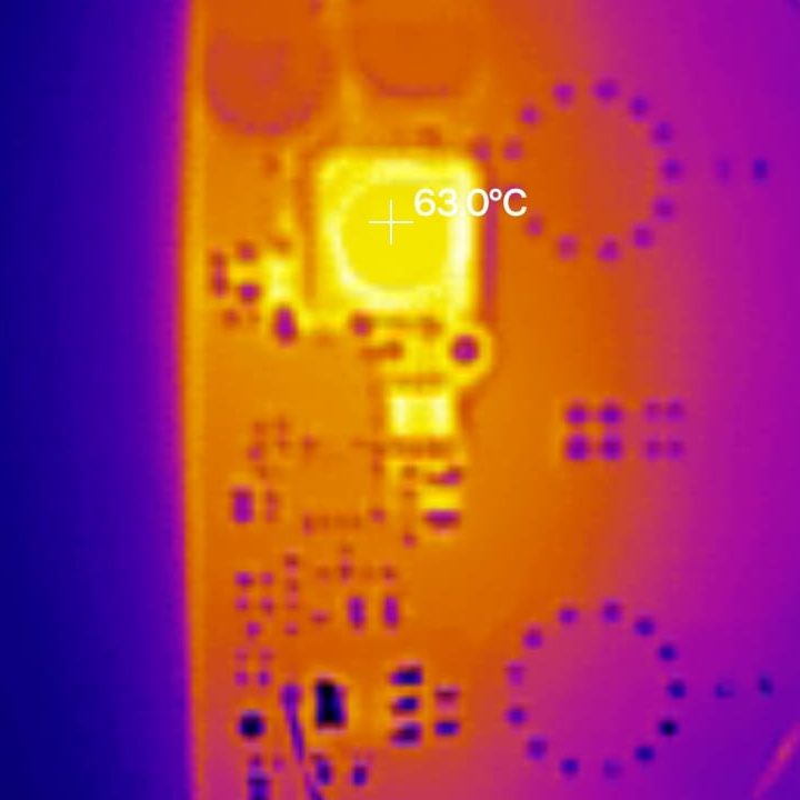
High excess heat means a low efficiency and likely a lower lifespan of components. The thermal behavior of revision one is not needed for analysis, as the supply is unfunctional. The thermal behavior under no load looks like this for the current revision:
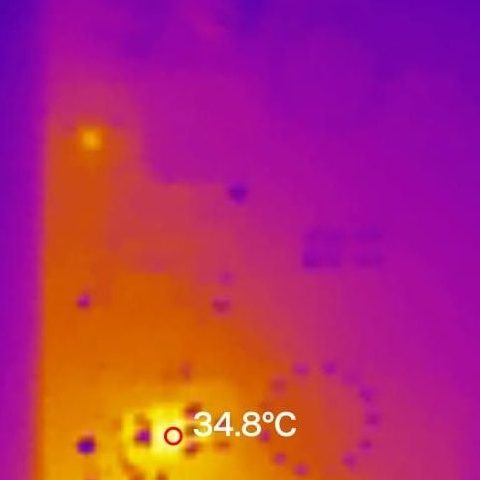
The hottest component on the PCB is the 3.3V voltage regulator seen in yellow
Under maximum load, after letting the board dwell 5 minutes, the PSU looks as follows:
The 3.3 uH inductor and FDS2762 get quite hot, but not too hot for operation. This temperature is deemed appropriate
Stability criterion
As the PSU experiences hardly any load step (different currents) and it is not too critical, stability margin improvements are neglected. Next to this, since the converter is running in DCM, this would be hard to determine.
Possible redesign
The UCC3803 and FDS2672 are also scarcely available at the moment due to the current semiconductor market situation, I might have to redesign the power supply in the future for different parts according to availability, pricing, and compatibility.
Leave a Reply