
Within my study association, I am active in the practical workshop committee called Volundr. As Volundr, we organize workshops such as PCB design, antenna design, IoT programming and soldering workshops. The soldering workshop used before was due for an update, which I decided to pick up.
The previous workshop featured a 5×5 addressable LED matrix of APA106 controlled by an ESP8266. This soldering workshop was soldering a header and 25 LEDs with narrow pin spacings, which was very troublesome for beginners. I wanted to make a more beginner friendly workshop featuring standard 2.54 mm pin pitch components.
As this idea spawned just 6 weeks before the actual workshop, a lot had to be done quickly in order to have all the components in time. I wanted at least a month of headroom for components to arrive and I counted 1 week to arrange all the approvals to buy the components. This left me with one week to think of and design a project.
As it has to be beginner friendly, I thought it would be fun to feature an astable multivibrator which controls a binary counter which in return counts up in an LED bargraph. My rough idea written down looked like this.
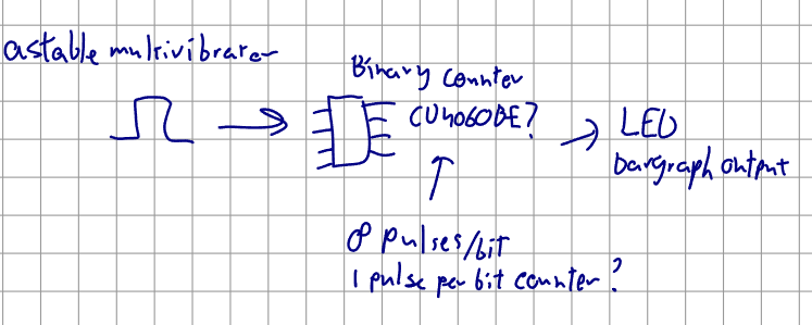
The idea was simple, however I was unsure if I wanted to use the CD4060BE binary counter, which needs 8 pulses per bit to update. I did some research and found the 74HC590, which updates for every pulse. Before we go into detail for this part, let us dive into the astable multivibrator first. The standard astable multivibrator circuit is very simple and looks as follows.
As you can see, there is a square output and an inverse square output. I wanted the oscillator to operate around 2 Hz. For this I set R = 220 \Omega,R1 = R2 = 10000 \Omega, C = 3.3 \mu F, V_{cc} = 5 V and for the transistors, I chose 2N2222 NPN transistors. This made the output frequency 1.94 Hz, which was in my opinion sufficiently close.

As for the 74HC590, according to the datasheet table 3, the N_OE and N_CE lines should be driven low to enable the output and the N_MRC should be high to get the IC out of reset. CPC and CPR should have opposing phases, which is perfect combined with our astable multivibrator doing that already. With this information, I designed the circuitry surrounding the IC as follows.
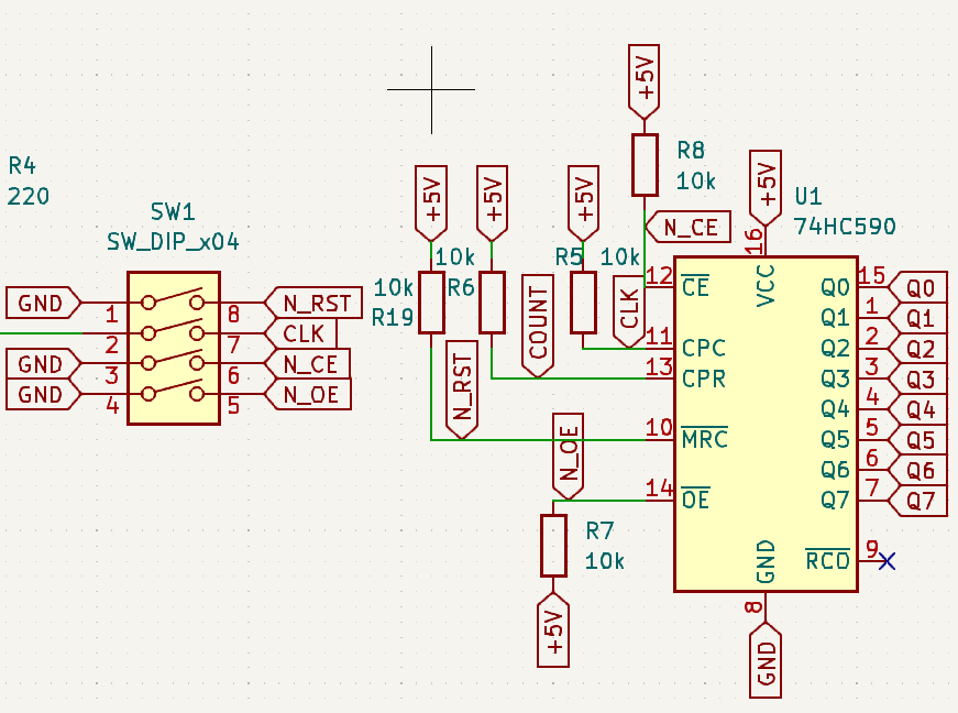
This leaves every input driven at all times preventing the death of the 74HC590 and switchable inputs for the operator.
The led bargraph is driven by the output of the IC through 220 ohm resistors to limit the voltage.
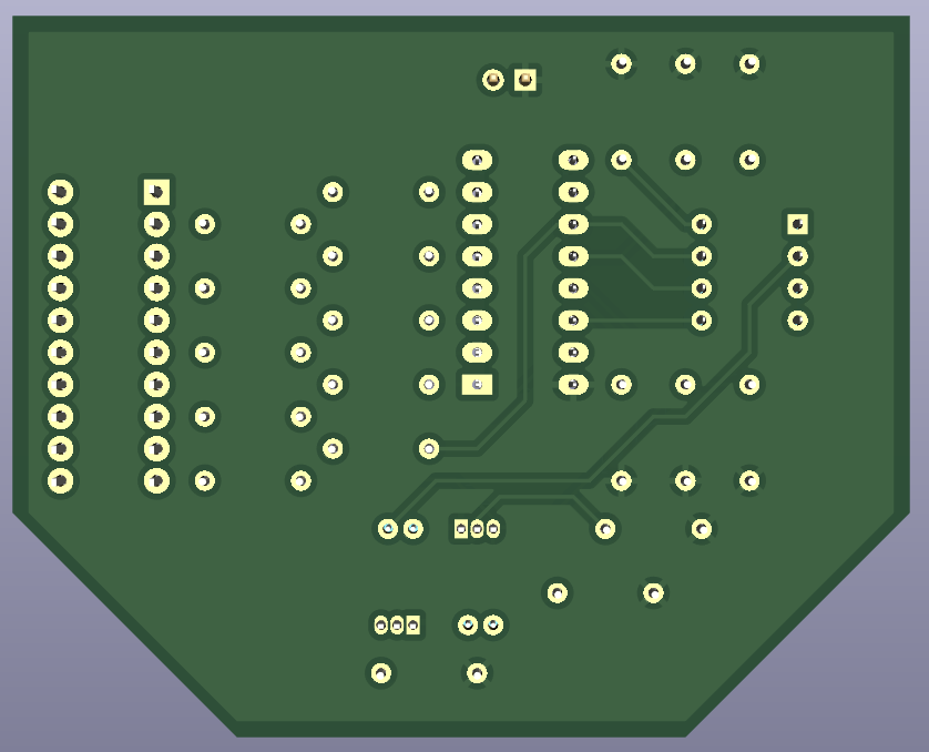
As the PCB should be beginner friendly, all connections and components are sufficiently spaced to become familiar with soldering and placing components. Next to that, all connections to copper planes should have thermal reliefs instead of full connections to ease soldering. This makes the final PCB look as follows
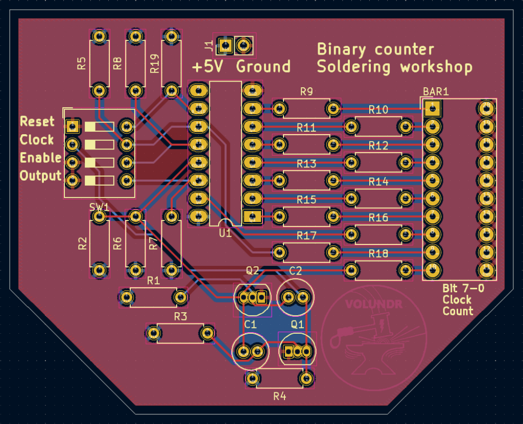
Or alternatively,
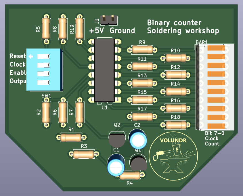
This should be very doable for a beginner and leave them with a fun little reminder of the workshop. Happy soldering!
Leave a Reply