
I am a member of ‘Ge Wit T Oit Noit Nie’, a participant of the annual Brabantse Dag wagon parade. The need to evolve the wagons’ electronic systems beyond simple switches has increased in order to stay competitive, creating the need for a modern, robust control system.
To address this, I designed multiple PCBs for different purposes that meet all needed safety requirements with a limited budget. The PCBs I designed are discussed below
Multi-purpose Microcontroller PCB
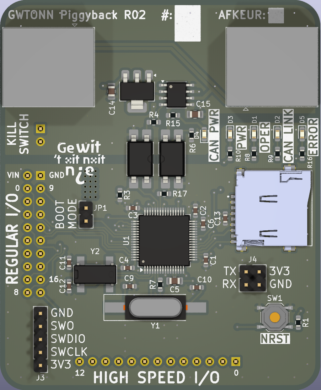
To reduce future design time, I created a modular microcontroller board containing all necessary communication interfaces and can plug into a main board to act as its brain.
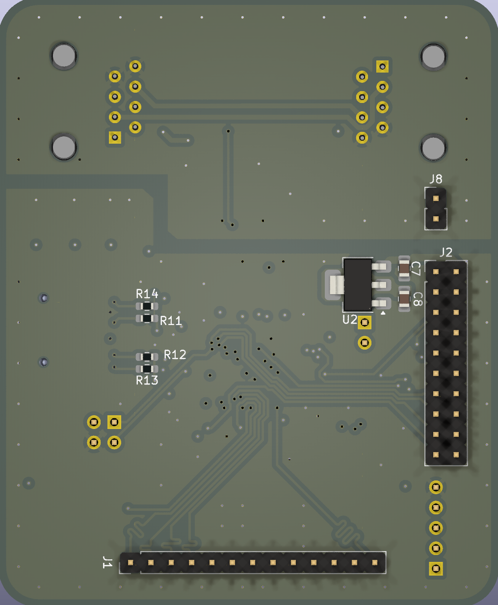
It was a requirement that it had to be field replaceable by someone who has no idea how it works. This is why all connections are numbered and the connectors are polarized. This way, they cannot be inserted incorrectly by accident.
Furthermore, communication between multiple boards had to occur. This is why we opted for the robust CAN bus, usually found in cars.
This implementation of the CAN bus was electrically isolated (up to 2~kV
Behind the optocouplers, a SN65HVD256DR handled the communication over the RJ45 connectors. Since it is fully electrically isolated, the RJ45 connectors also had to carry 12~V
The microcontroller that was used is the STM32F412RGT6, which is a LQFP64 controller from STMicroelectronics. An 8~MHz passive resonator and a 32.768 kHz crystal resonator provide accurate clocking for timekeeping and SPI operation.
To log everything that is going on on the board, a microSD card slot is added which uses aforementioned SPI bus. The microcontroller writes time-stamped data to it as well as to the CAN BUS.
To view the system statuses, LEDS are added to see at a quick glance whether the board has power, CAN has power, there is a CAN link and whethet the system is in error.
In case there is an error, this is sent to the SD card and over the CAN BUS to the master board, which is described later.
The board also features 13 high-speed and 17 regular IO which are routed out to the connectors on the bottom. The high-speed IO are all length matched within 0.5 mm such that they can carry high frequency signals.
Master controller
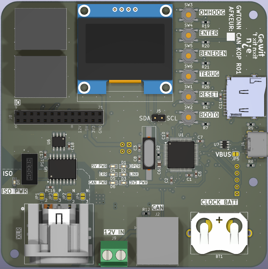
The master controller features the same microcontroller as the multi-purpose board although it is configured slightly differently. On this board, a RTC clock battery is placed which keeps time when the board is turned off. This is done as the board will not be constantly powered and loss of time is quite annoying. To view incoming messages and read through them, buttons and an I2C screen is added to make debugging in the field easier.
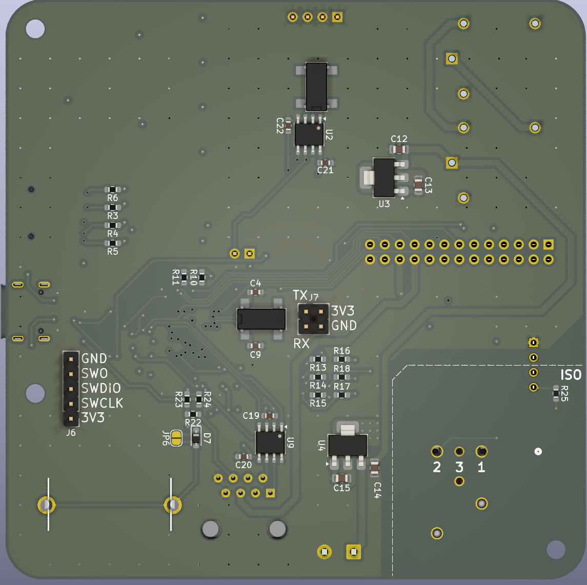
For the emergency stop, two relays are put in series which will cut 12~V power to the entire wagon.
This board also has a DMX input which is electrically isolated from the rest of the board using an isolated supply. This enables our music technician to program some stuff through DMX.
Next to that, this board can be programmed and read out with USB-C. The USB-C connection is protected from voltage transient, is impedance matched and is length matched.
Next year around this time, we will know whether this engineering effort was worth it!
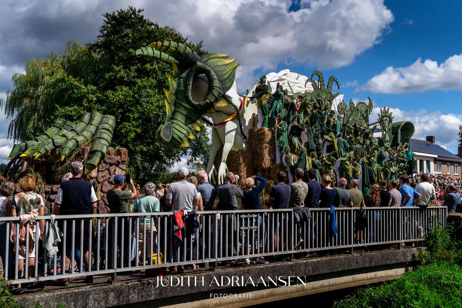
As a bonus, here is the wagon (and a shoutout to Judith Adriaansen).

I sincerely hope to enjoyed the read. Let me know what you think!
Leave a Reply