
I recently upgraded from my trusty Rigol DS1054Z to a Rigol DHO924 as I was in the market for a higher bandwidth 12-bit oscilloscope with logic analyzer capability. Whilst purchasing the oscilloscope, I noticed that the price of the logic analyzer it pairs with is above 300 euros, WAY too much for a function I was not going to use too often. I decided to scour the internet and find a DIY alternative.
That’s when I stumbled upon an EEVBlog forum and particularly this version of the DIY probe. When I inspected more closely, I noticed a few things that I could improve upon such as length and impedance matching, as well as routing the differential pairs more efficiently.
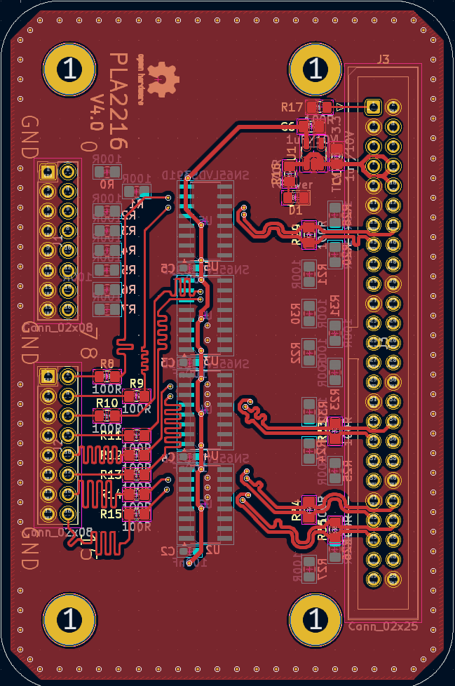
The schematic from Nikki Smith is completely fine, and thus copied for my PCB design.
The drivers for the signal are SN65LVDS391D which is a Quad LVDS Line Driver, they can tolerate input voltages up to 5 V, which is fine for my logic applications as they are mostly 3.3 V. This part specifically, is designed to drive 100 Ω differential pairs, which is what I based my impedance match on using the built-in calculator in KiCAD and the dielectric values from JLCPCBs FR4. The traces have been length matched up to 0.5 mm on the input side and 0.5 mm on the output side.
They are powered by the TLV743P33, which is a 3.3 V Low Dropout Linear Regulator.
The LED within the schematic is left unassembled for my purposes, but is included in the PCB design.
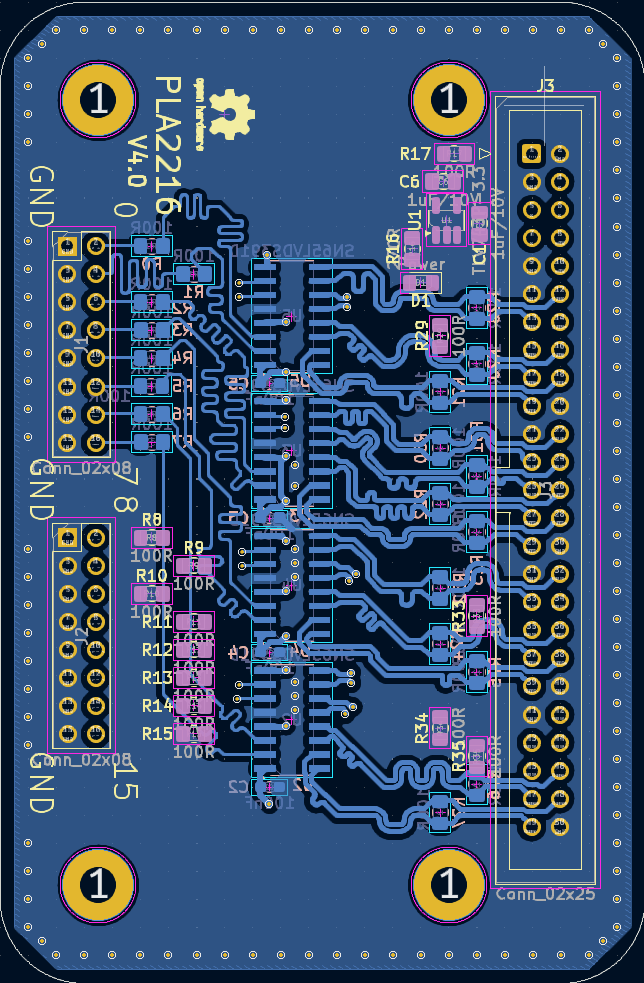
The designed PCB is a 2-layer PCB:
On Nikki’s website, I saw that the 50 pins connector had to be flipped for easy installation in the oscilloscope, this turned out not to be true after production. In the next revision, this will be corrected. Next to that, ground vias will be placed near differential pair vias to increase integrity. Overall, I am quite pleased with the PCB and its operation as it does work flawlessly. It has been tested up to 160 MHz and performed okay.
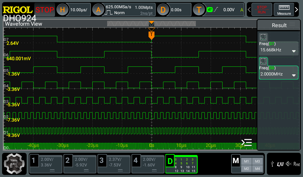
Over here, it can be seen in action with an 8-bit counter counting at 4 MHz, which leaves the LSB at 2 MHz.
Since there are still some things that need improving, it will be updated some time in the future, for now, the files can be downloaded below.
EDIT 15-09-2025: It seems someone made a case for it! https://www.thingiverse.com/thing:7015417/apps
Leave a Reply